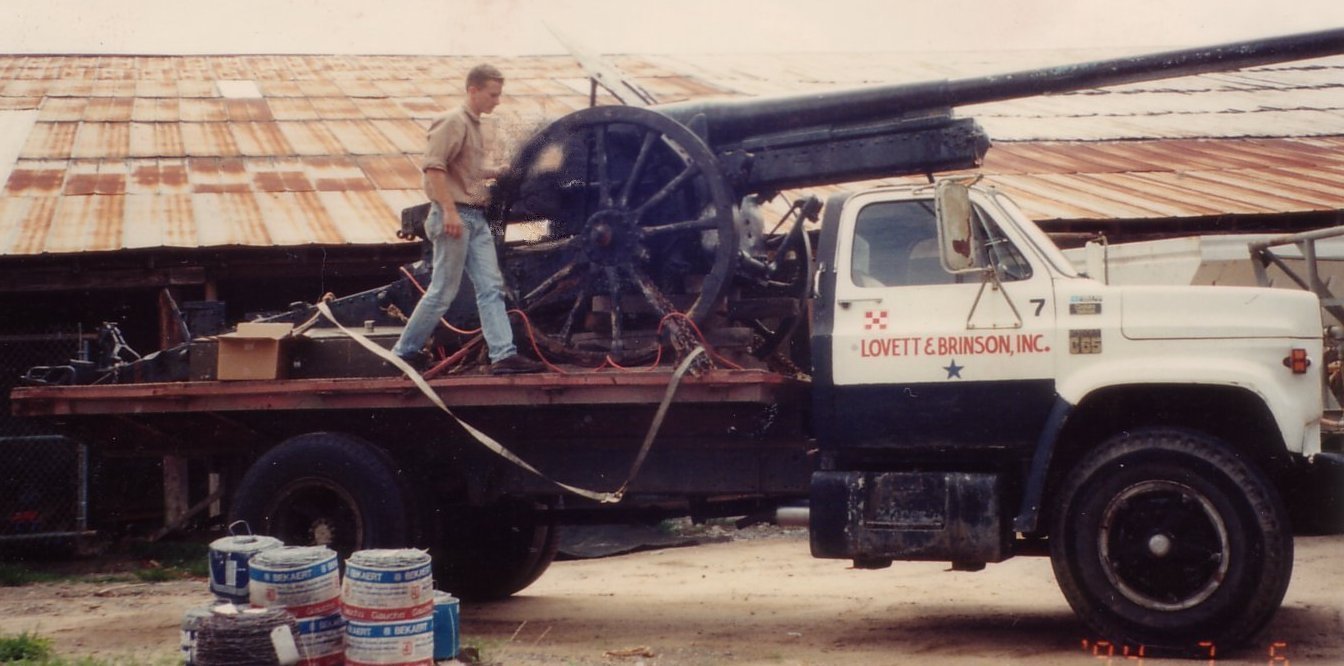
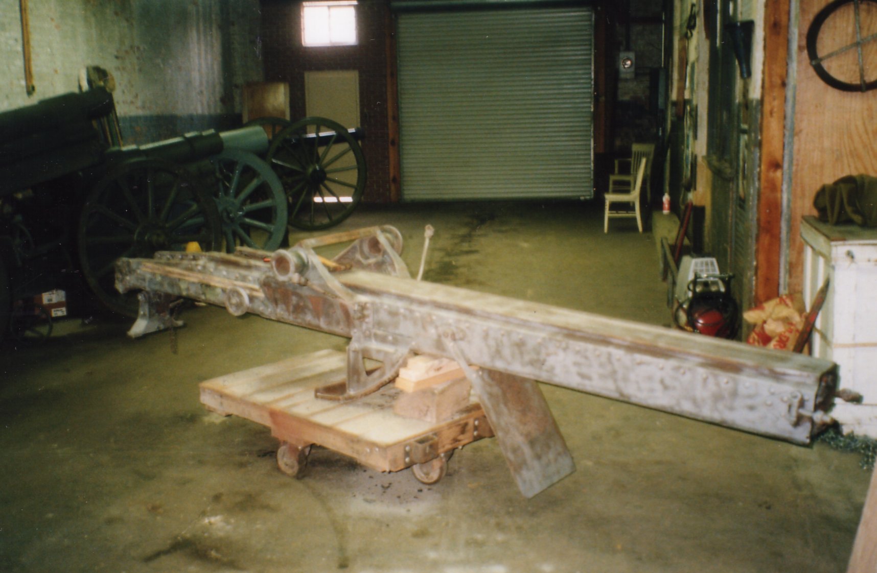
The 10cm Kanone 1917 before restoration.
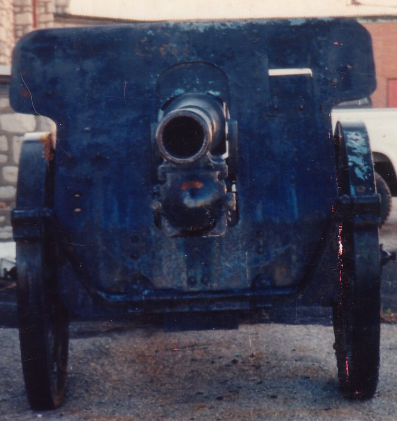
A front view of the 10cm K 17. Before disassembly, the field gun’s overall condition seemed good. Unfortunately, this proved not to be the case.
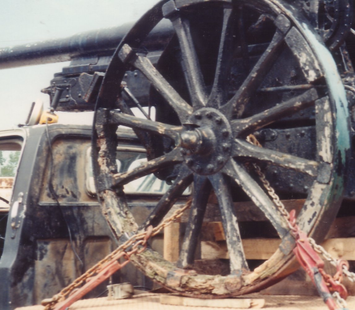
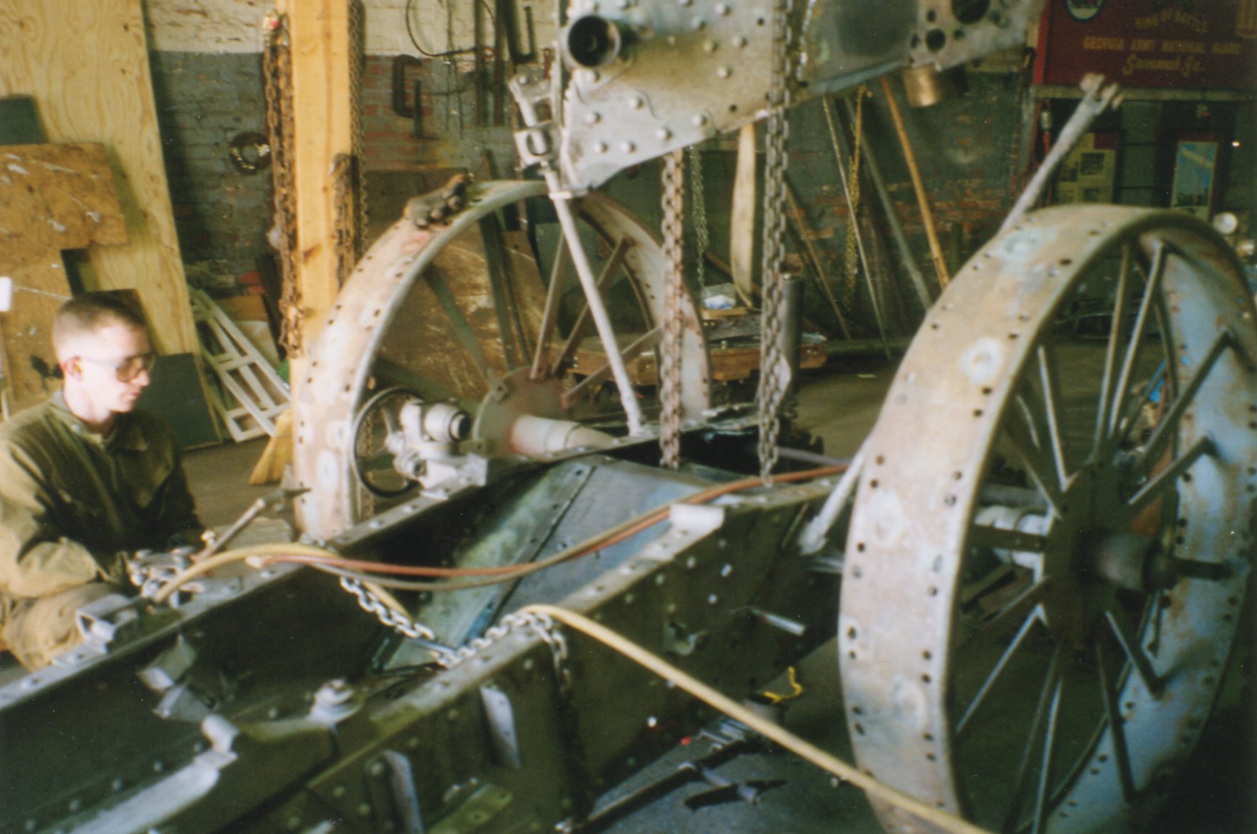
Wheels in need of restoration. These wheels were sent out to Charley Crenshaw in South Carolina for restoration. Charley finished the work about the same time I finished the restoration of the gun. Charley died some months after completing the wheel restoration. In the mid-1980s, he also restored the excellent set of wheels on our 15cm sFH “93.
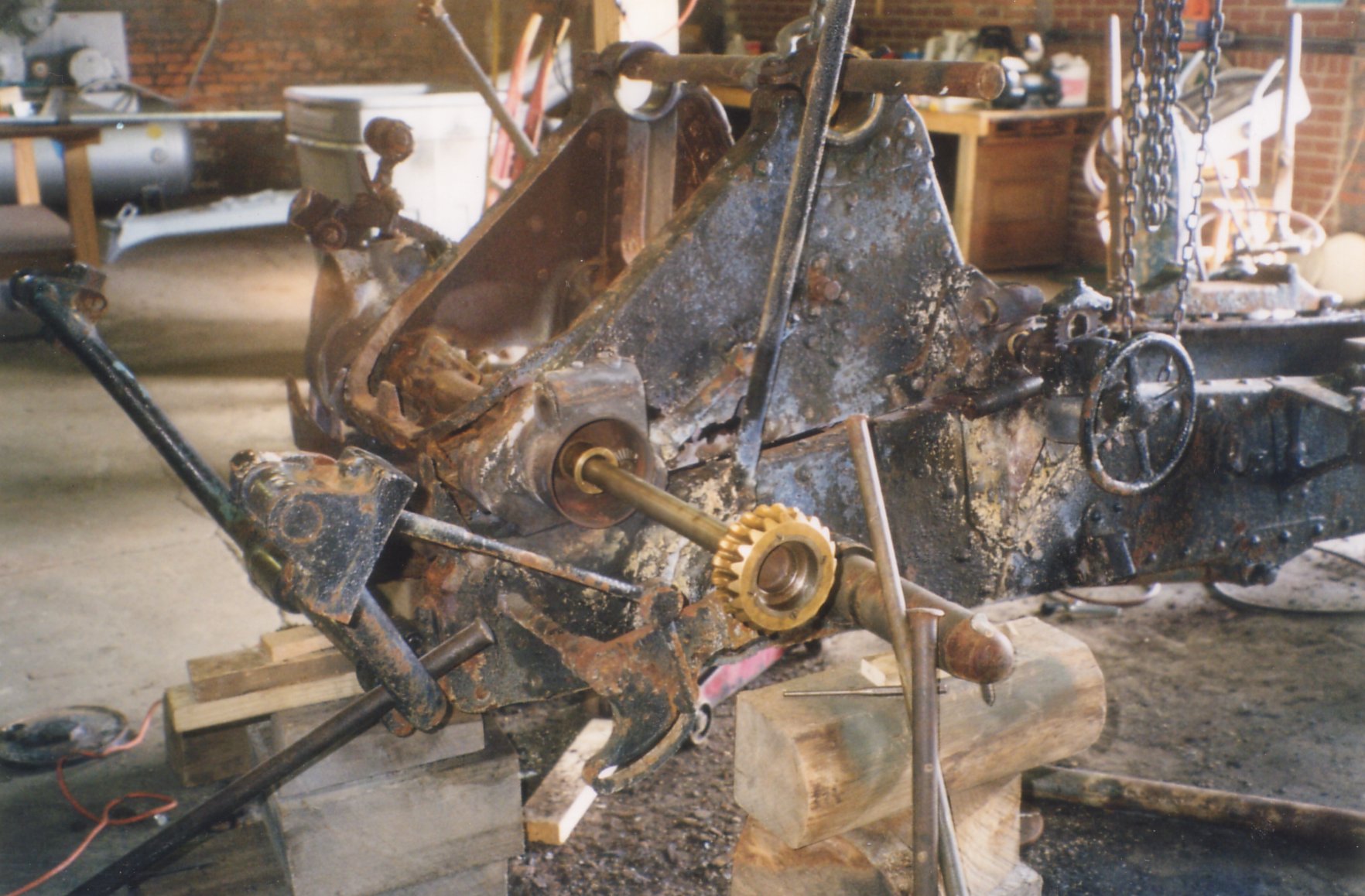
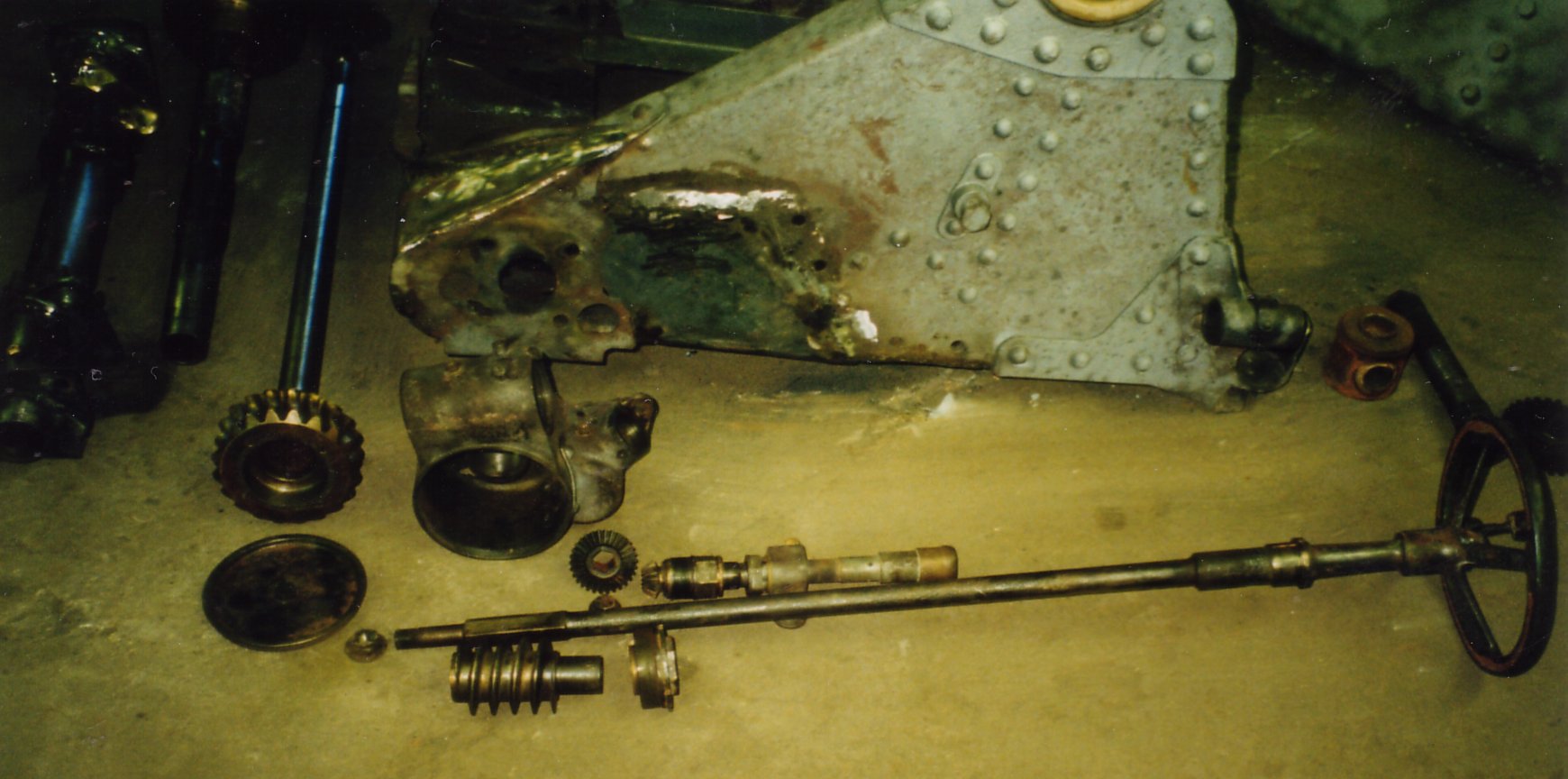
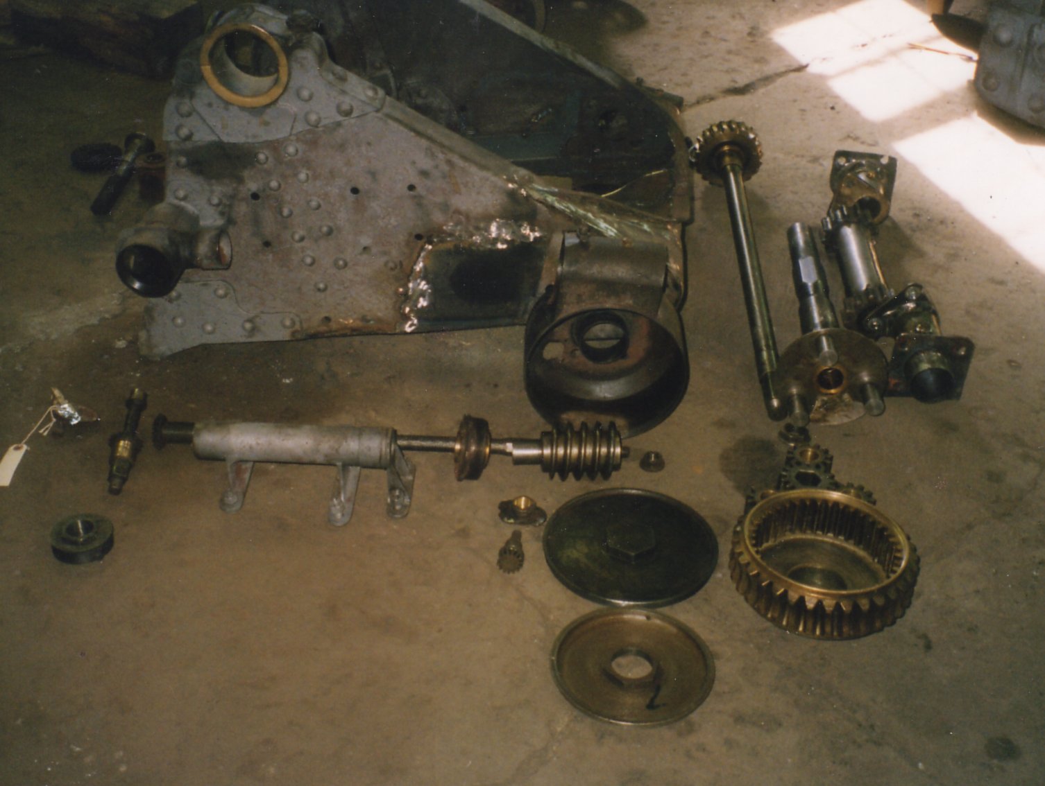
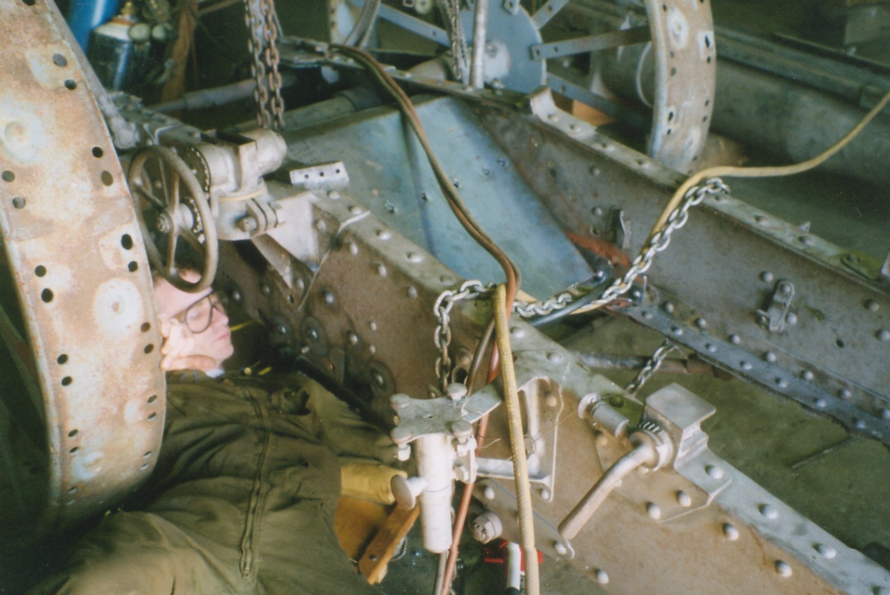
Removal of the sight elevation gear and shaft.
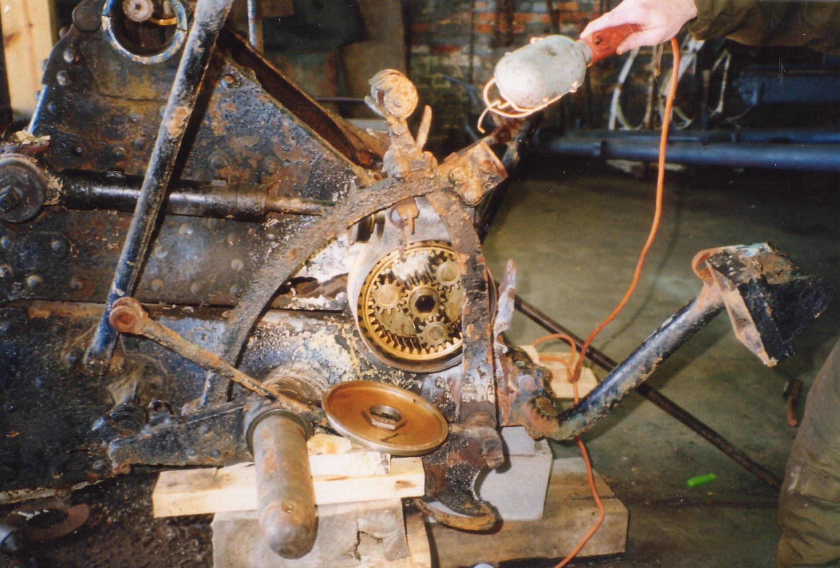
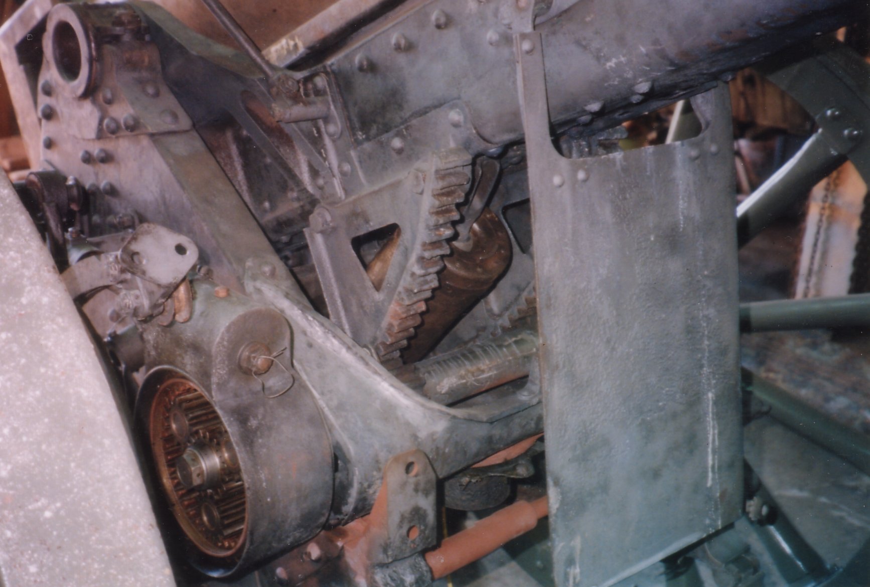
The range elevation planetary gear with cover removed. The planetary gear allows the sight elevation gear to turn independently within the range elevation gearing. Obviously, this system is very complicated. To me, it is surprising that this overly complicated elevation system was still manufactured, in this way, even in the later part of the war. I believe, this system was used mainly to allow quick adjustment of elevation. The original plan for this gun was for it to double as an anti-aircraft/balloon gun. Presumably, sight elevation figures would be calculated last as an aircraft approached. I believe, this is why a two part system was developed for range elevation and sight elevation. (see 10cm Development article) Any other theories would be welcomed.
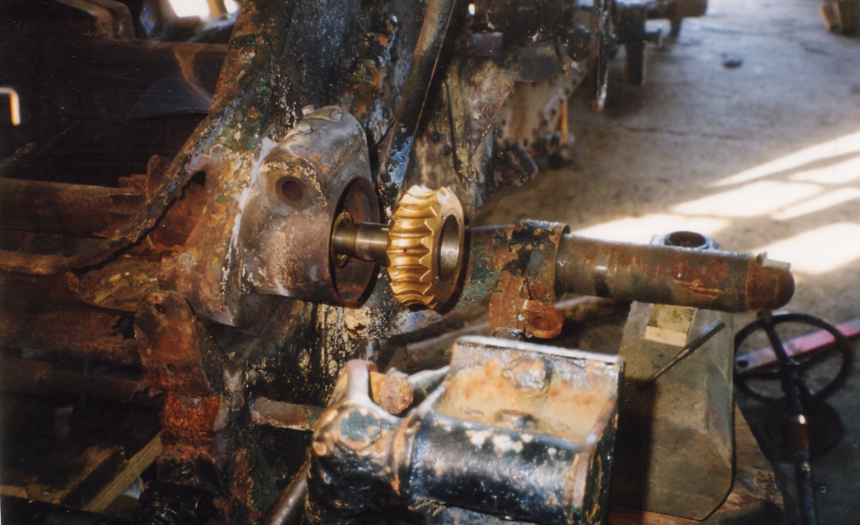
A close-up of the sight elevation gear.
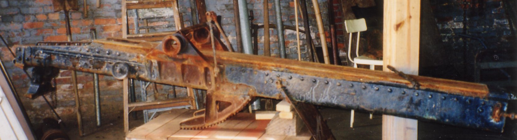
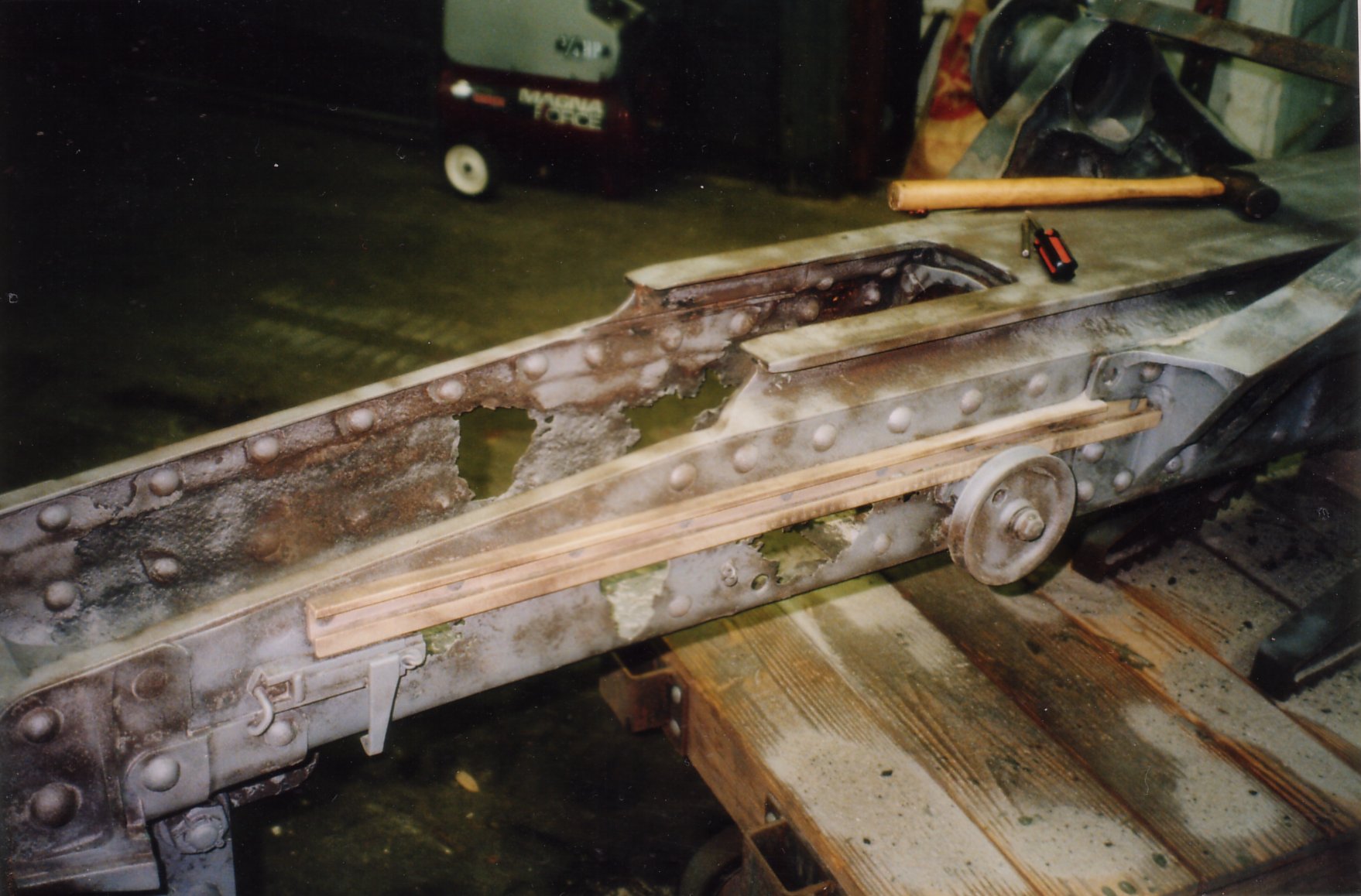
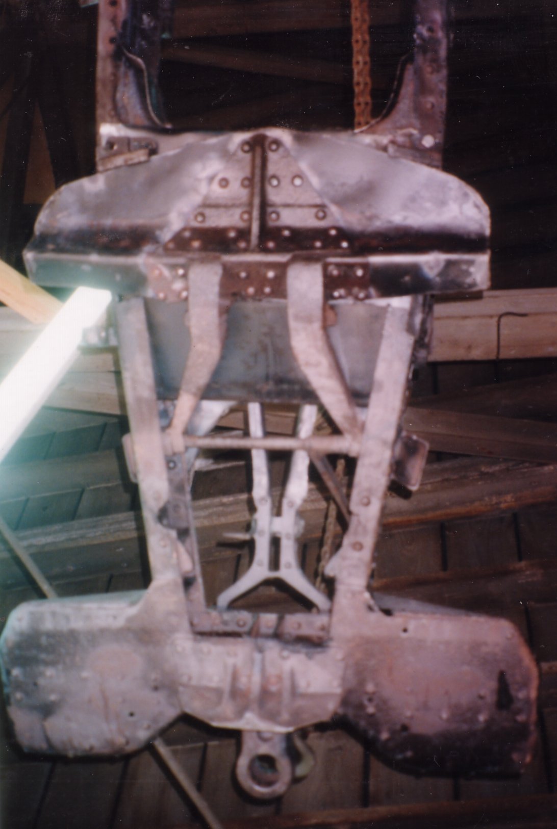
The carriage trail with sheet metal in very poor condition.
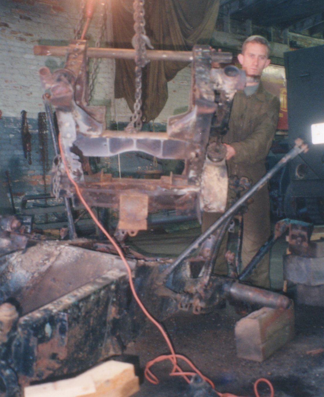
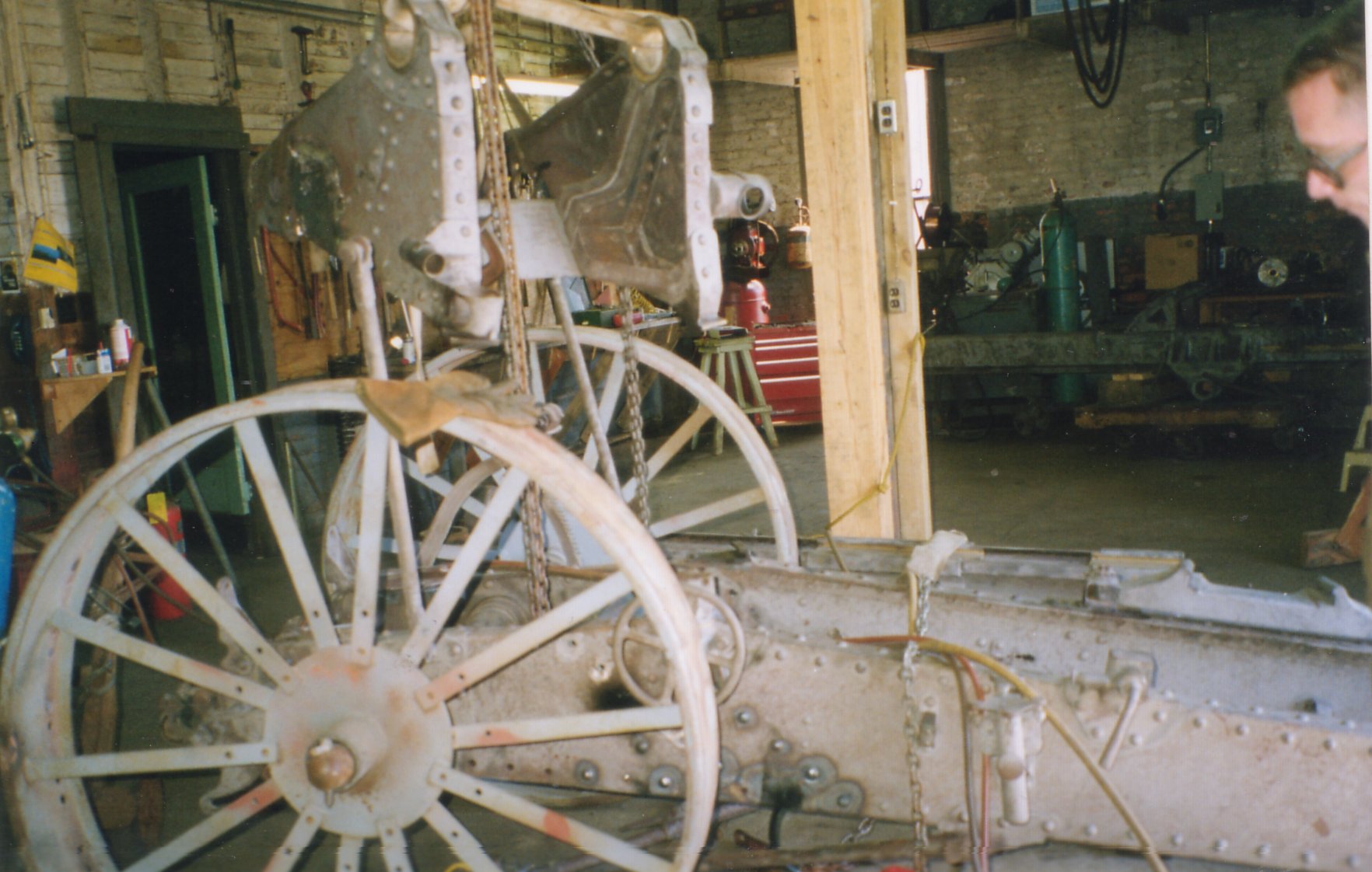
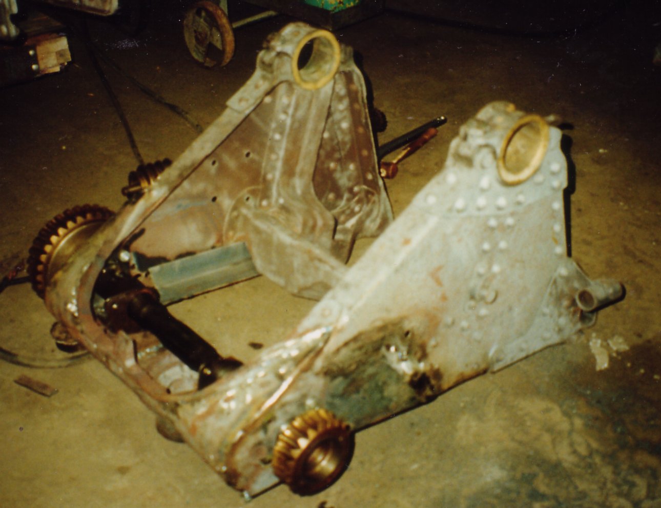
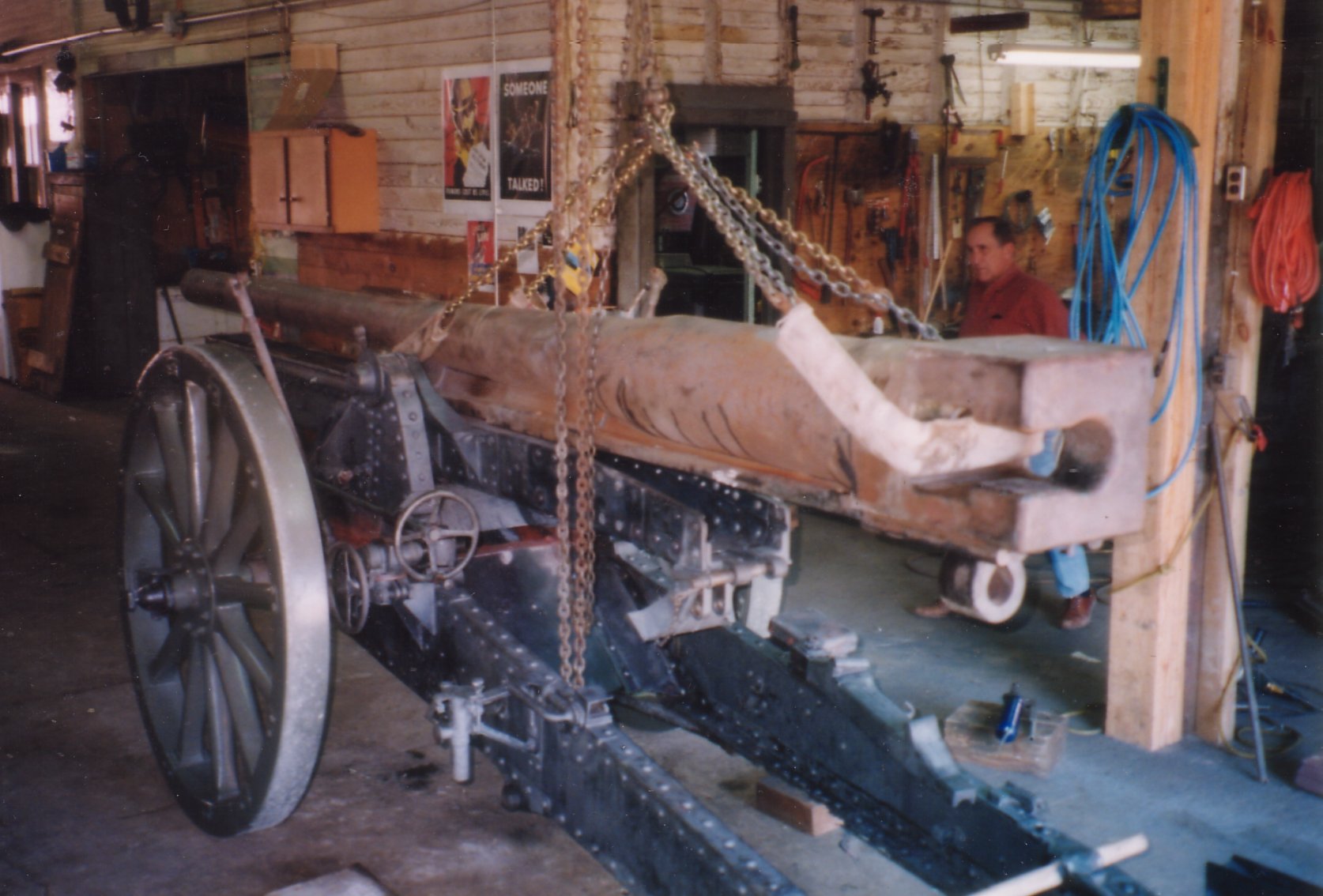
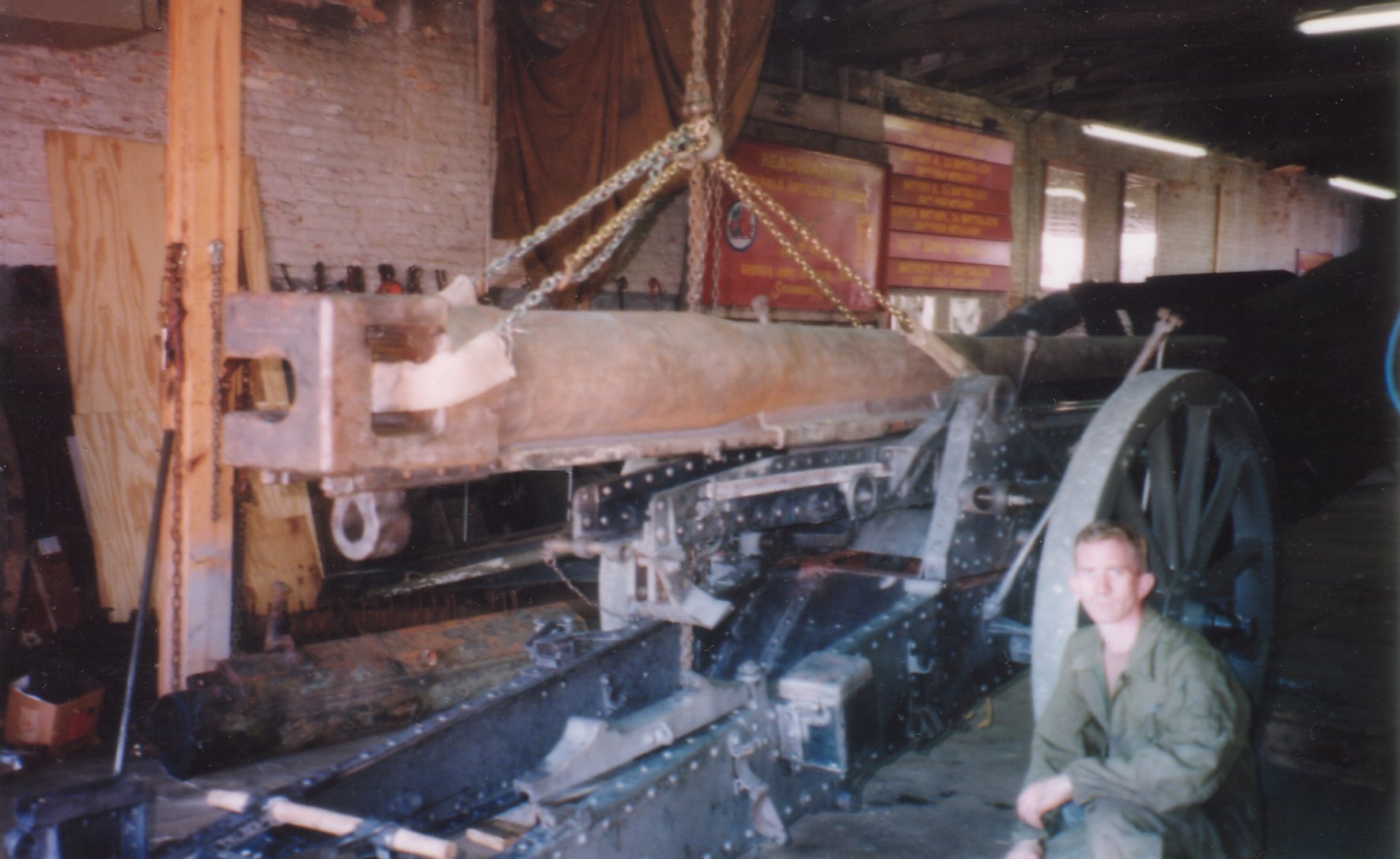
The cheeks hoisted up and off the carriage.
The cheeks, with the elevation gearing visible, is hoisted off the carriage. The overall poor condition is evident in this photograph.
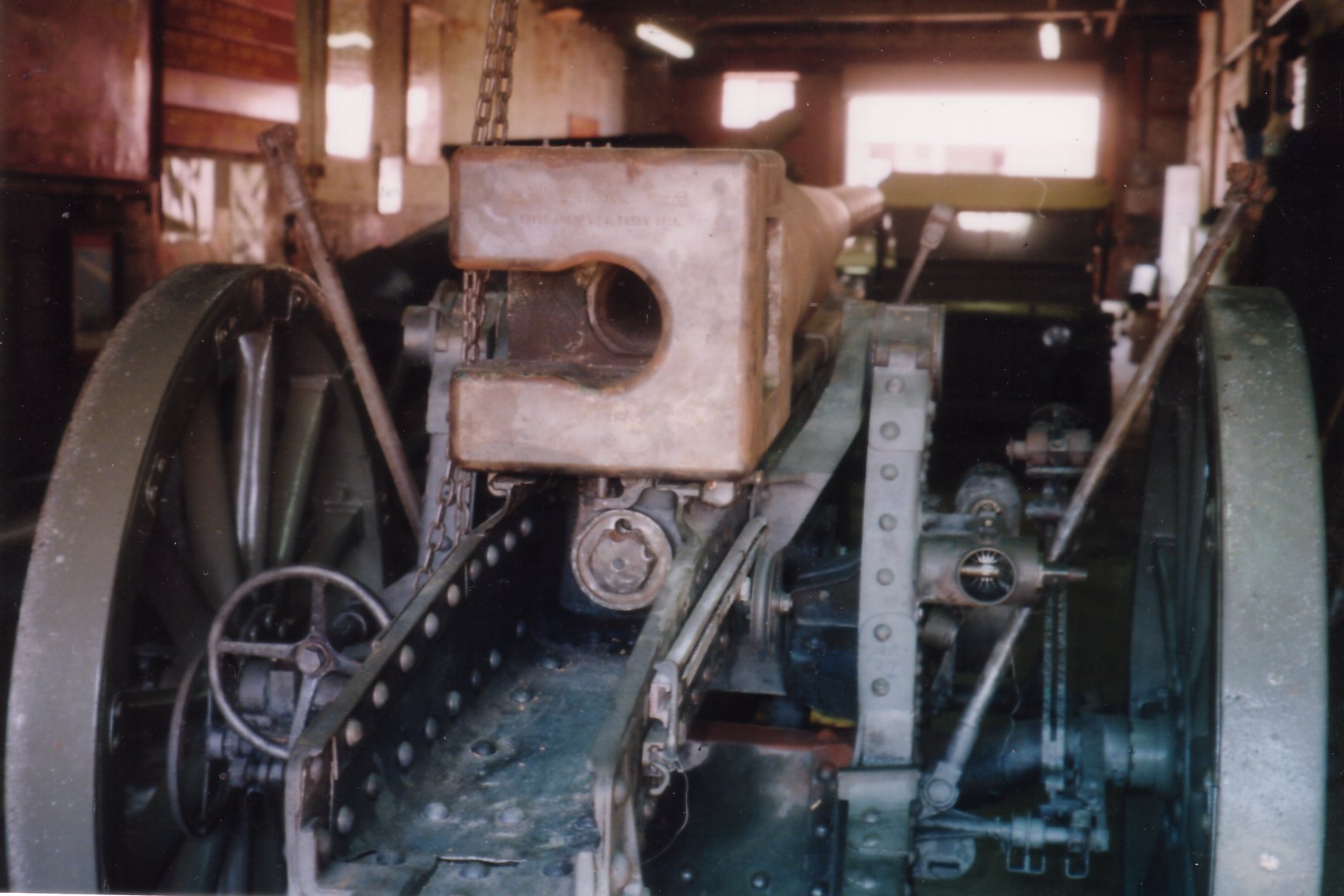
A close up of the cheeks with the elevation gearing.
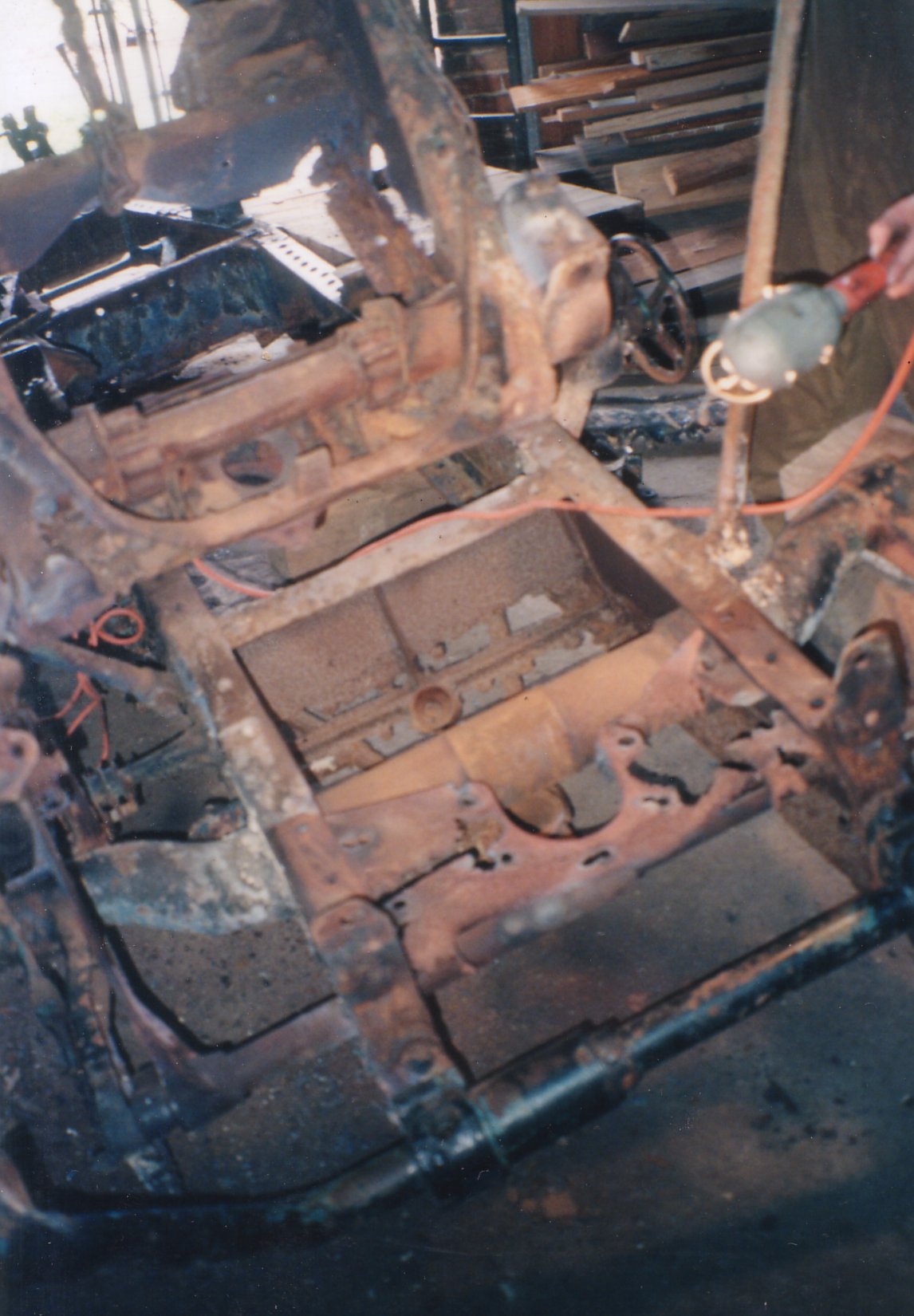
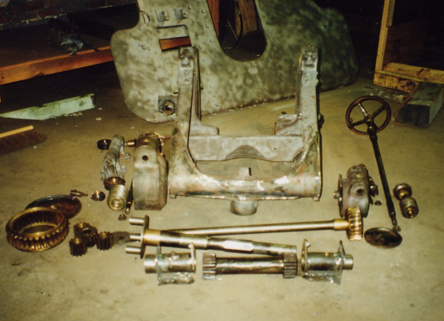
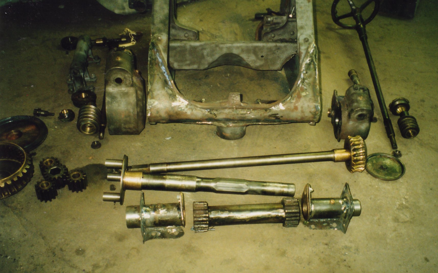
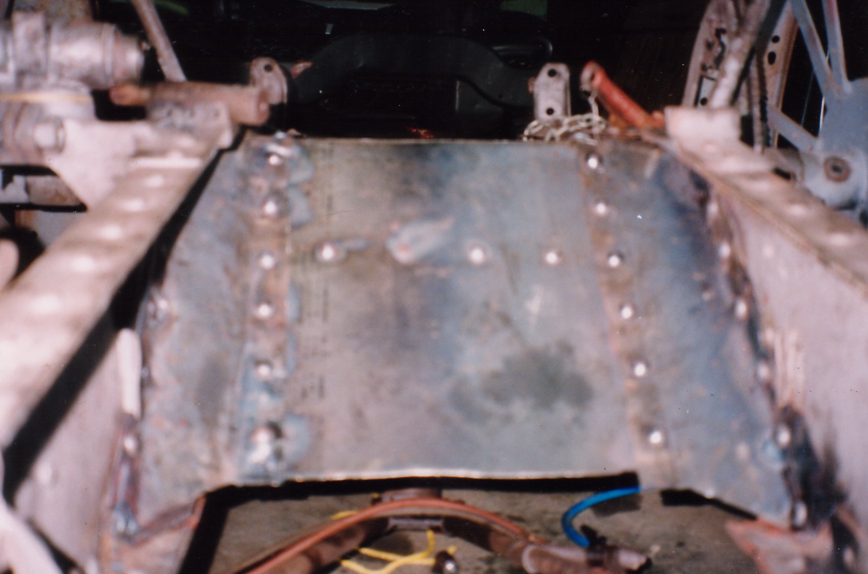
The interior of the cheeks with the elevation gearing removed.
Another view of the cheeks with the elevation gearing stripped out.
A view of the exterior of the cheeks with most excessive rust and deterioration removed.
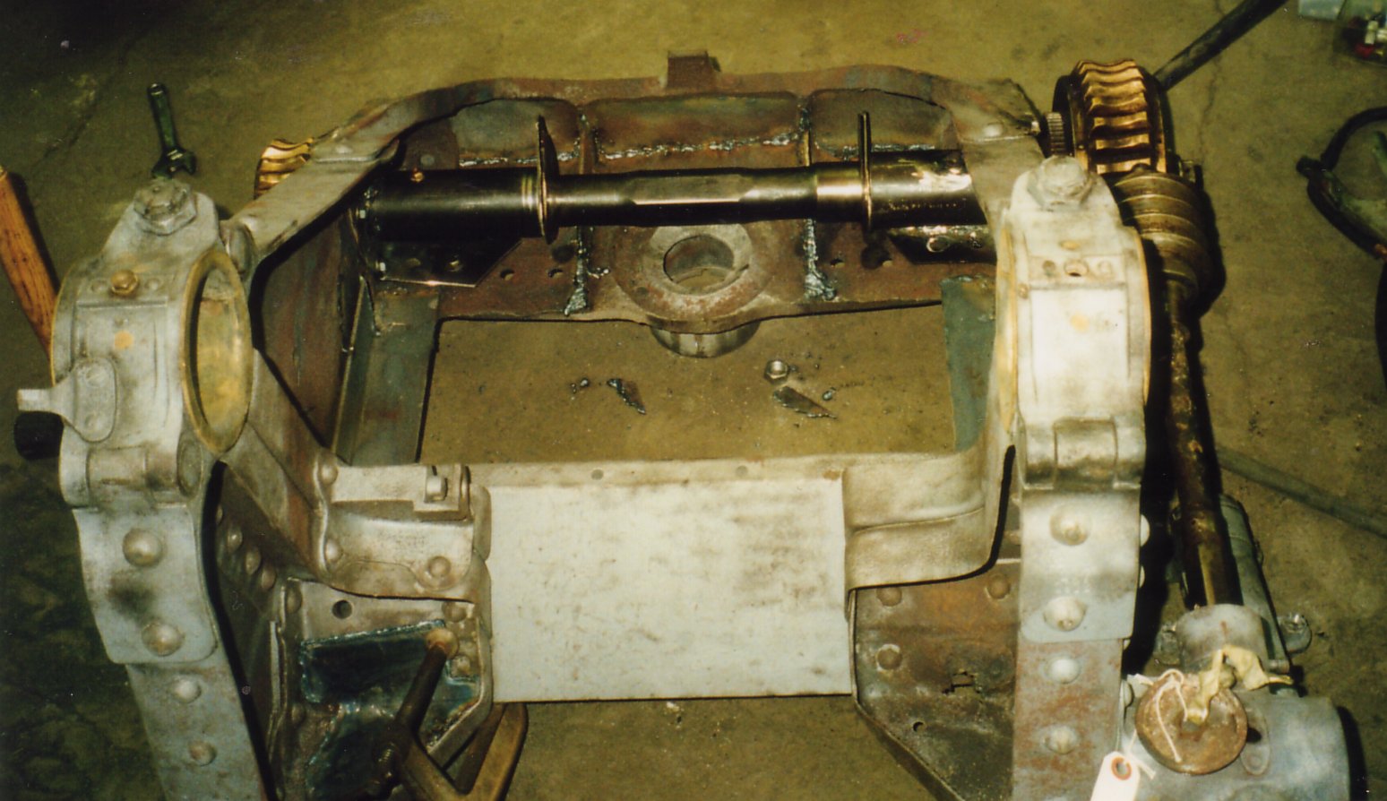
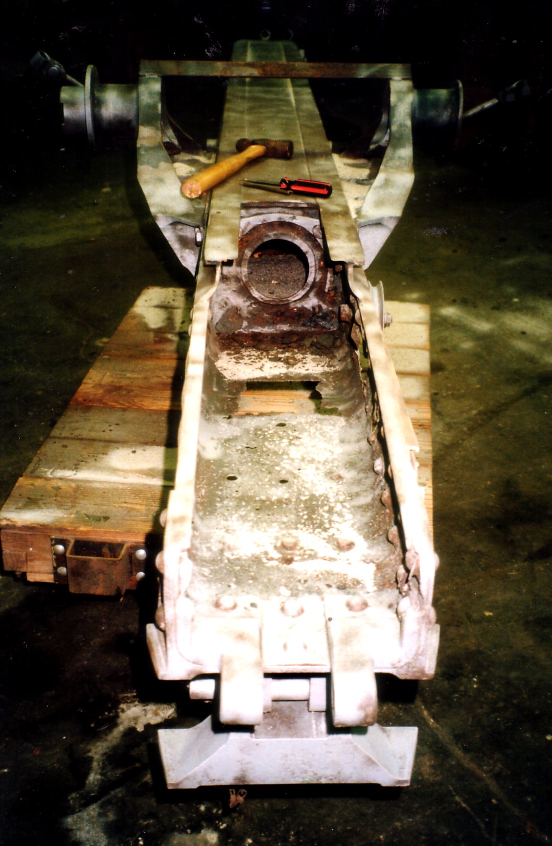
In this interior photograph, the pivot point for the traversing mechanism is evident.
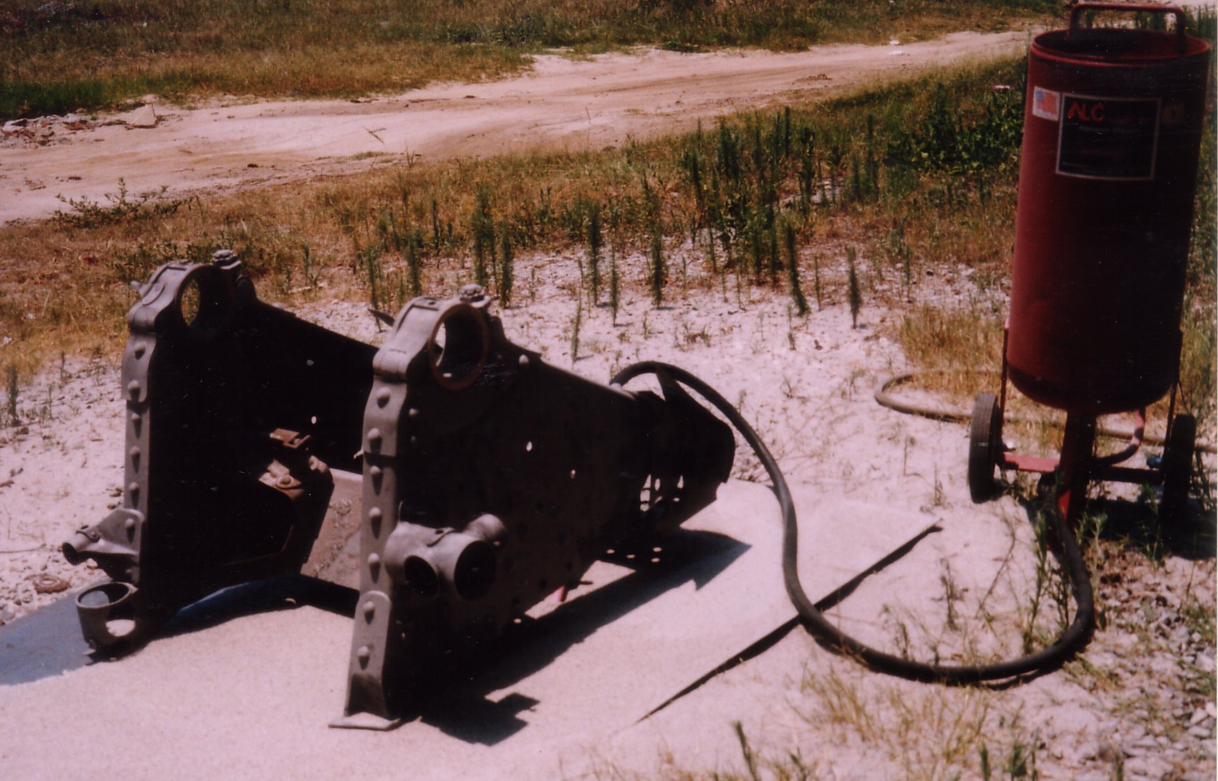
Sandblasting the cheeks.
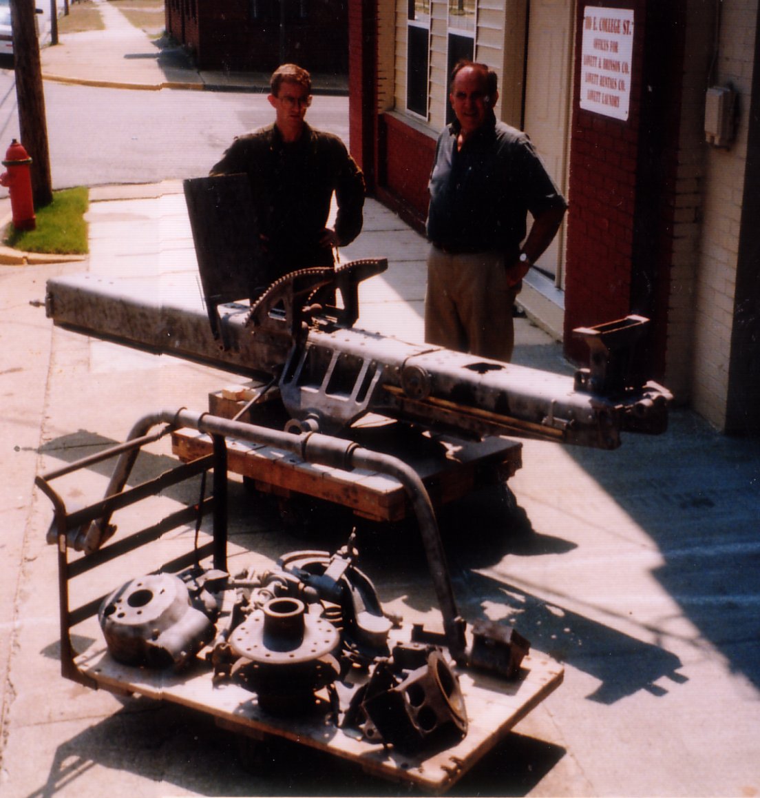
Ralph and Leon standing with the recoil cradle (upside down on the far dolly). Sitting on the nearer dolly are the range and sight housings for the elevation mechanism. The wheel hub is for the 10,5cm lFH 16.
Placing the cheeks back on the carriage. The iron wheels on the carriage are temporary wheels used only while the original wheels where being re-built. Some of the new riveting is evident on the side of the carriage in this photograph.
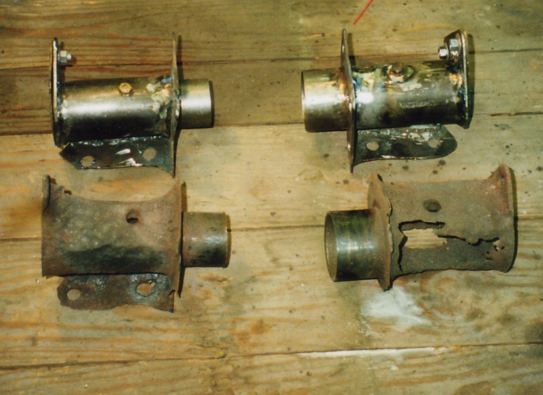
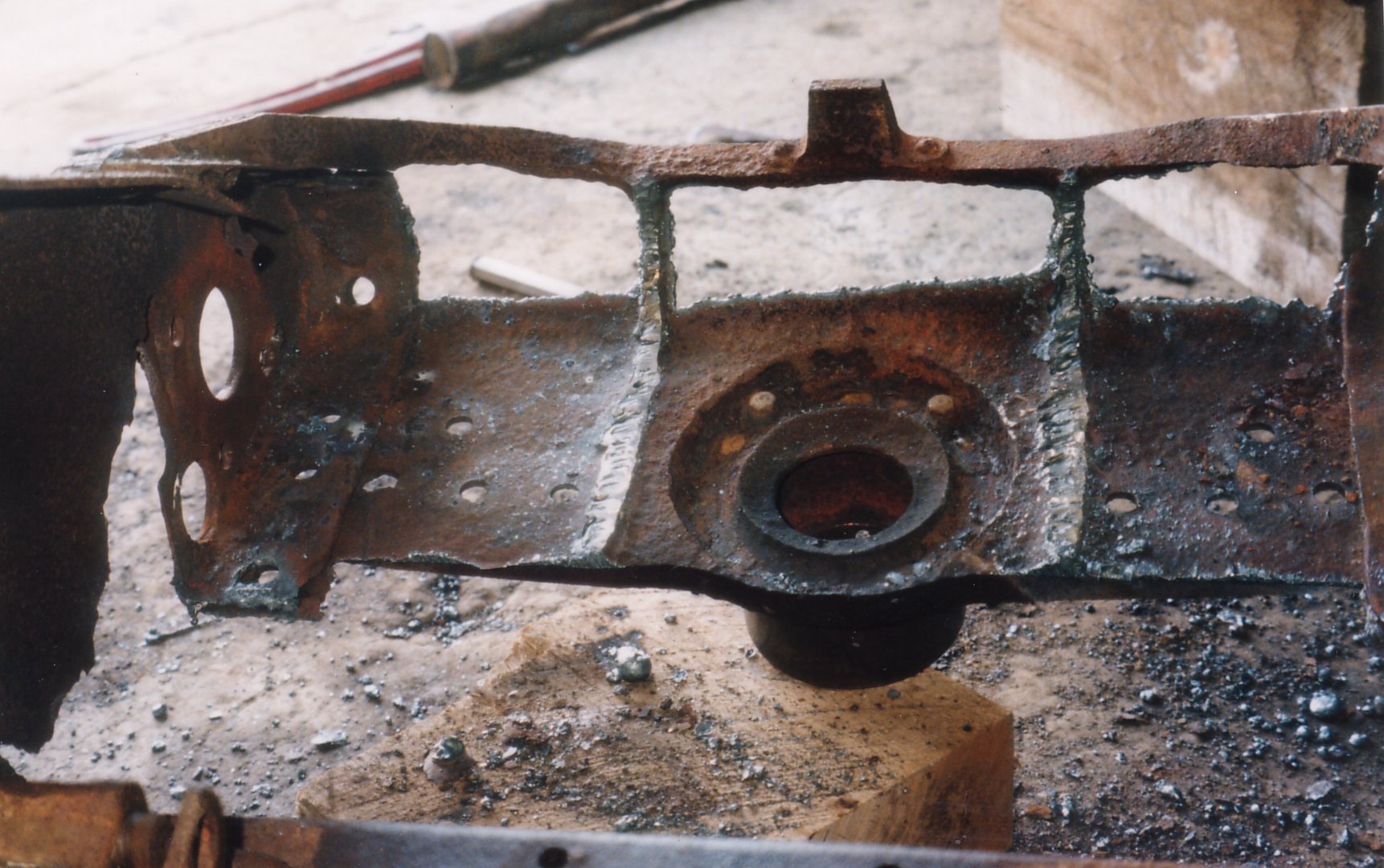
New and old mounts for the elevation mechanism. The extreme rust-through is obvious in this photograph.
Welding sheet metal and angle iron into place on the cheeks. For the most part, I try to use methods which were available during the time period the howitzer or gun was in service, however, in this case the damage was too severe. Metal Inert Gas or “MIG Welding” (not available in WW1) was the only reasonable and available option.
Sight elevation gearing with the re-built cheeks laid out and ready to be reassembled.
Range elevation gearing with the re-built cheeks laid out and ready for reassembly.
A front view of both the range and sight elevation mechanisms. Because of the number of parts and complexity of this system it was necessary to fit everything together first with bolts, then make sure both range and sight elevation systems worked smoothly, then remove one bolt at a time, replacing each with a rivet. This was a very time consuming process but was eventually successful.
A close up of the two elevation systems.
Photograph with the new elevation mounts fitted into place. This was just to test the alignment of the elevation gearing. The gear housings are not yet in place.
A side view of the cheeks with the sight and range gearing in place but without the housings.
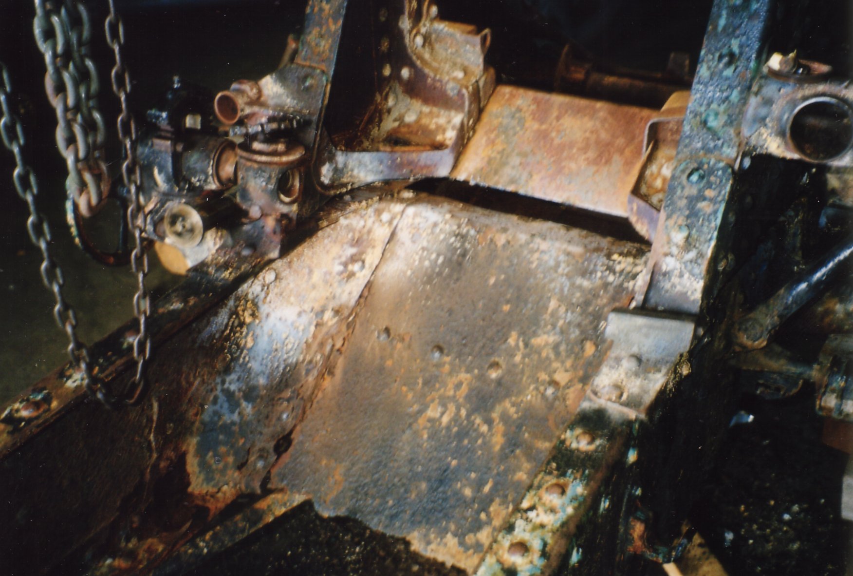
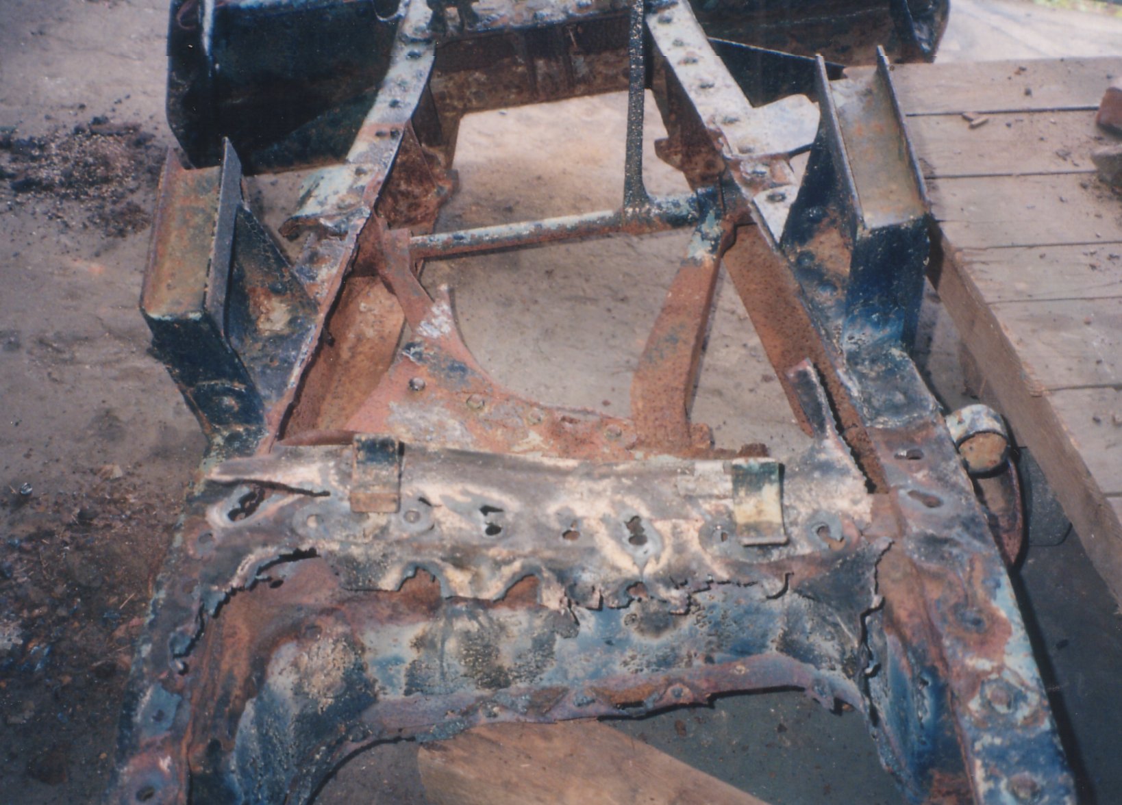
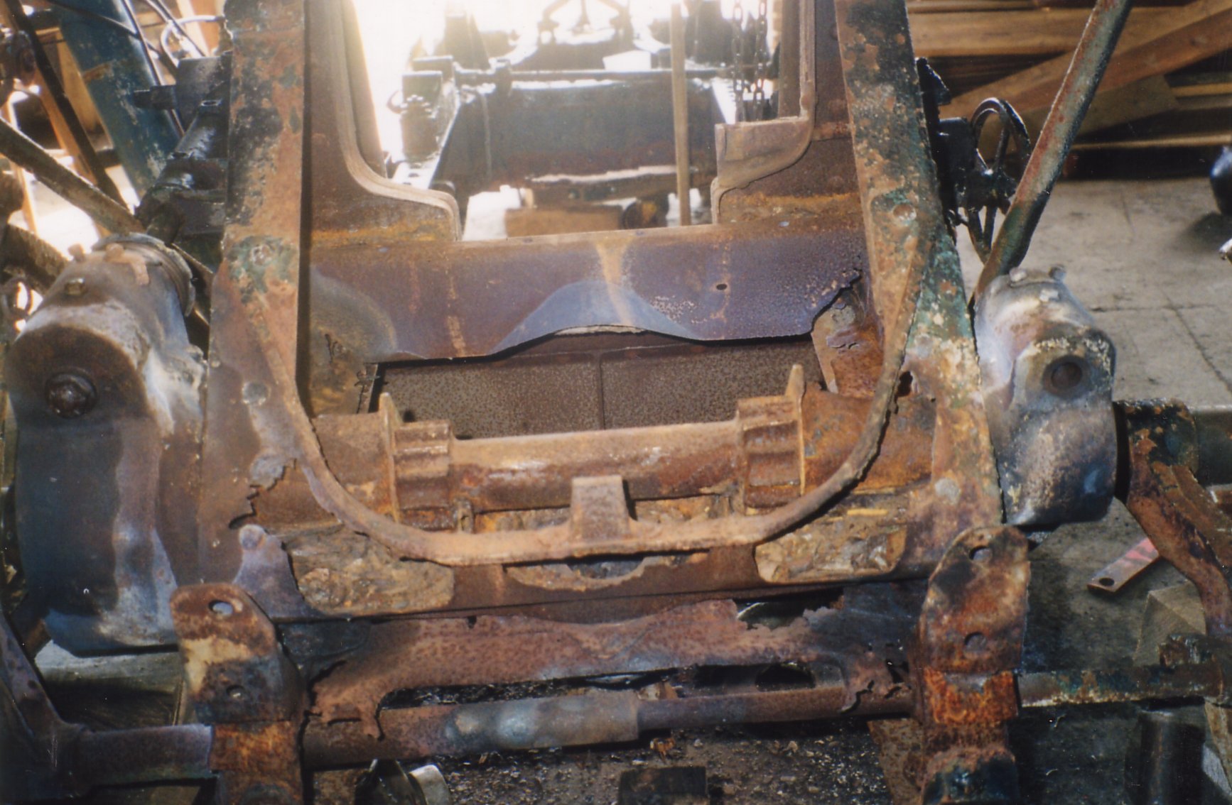
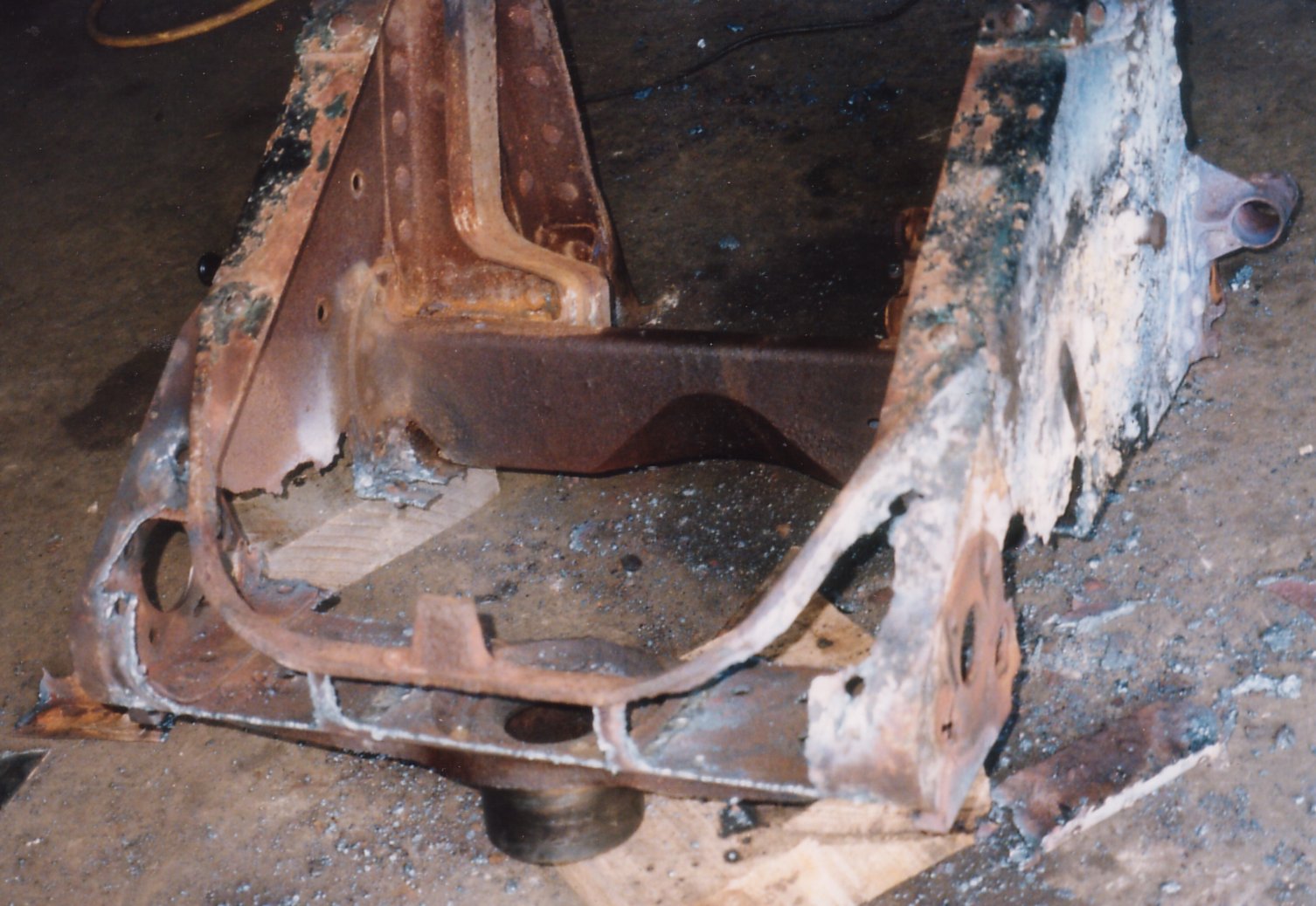
Sloping sheet metal coving the equilibrator on the carriage. The poor condition of this sheet metal is evident here but underneath, the frame mount for the equilibrator, was much worse than expected.
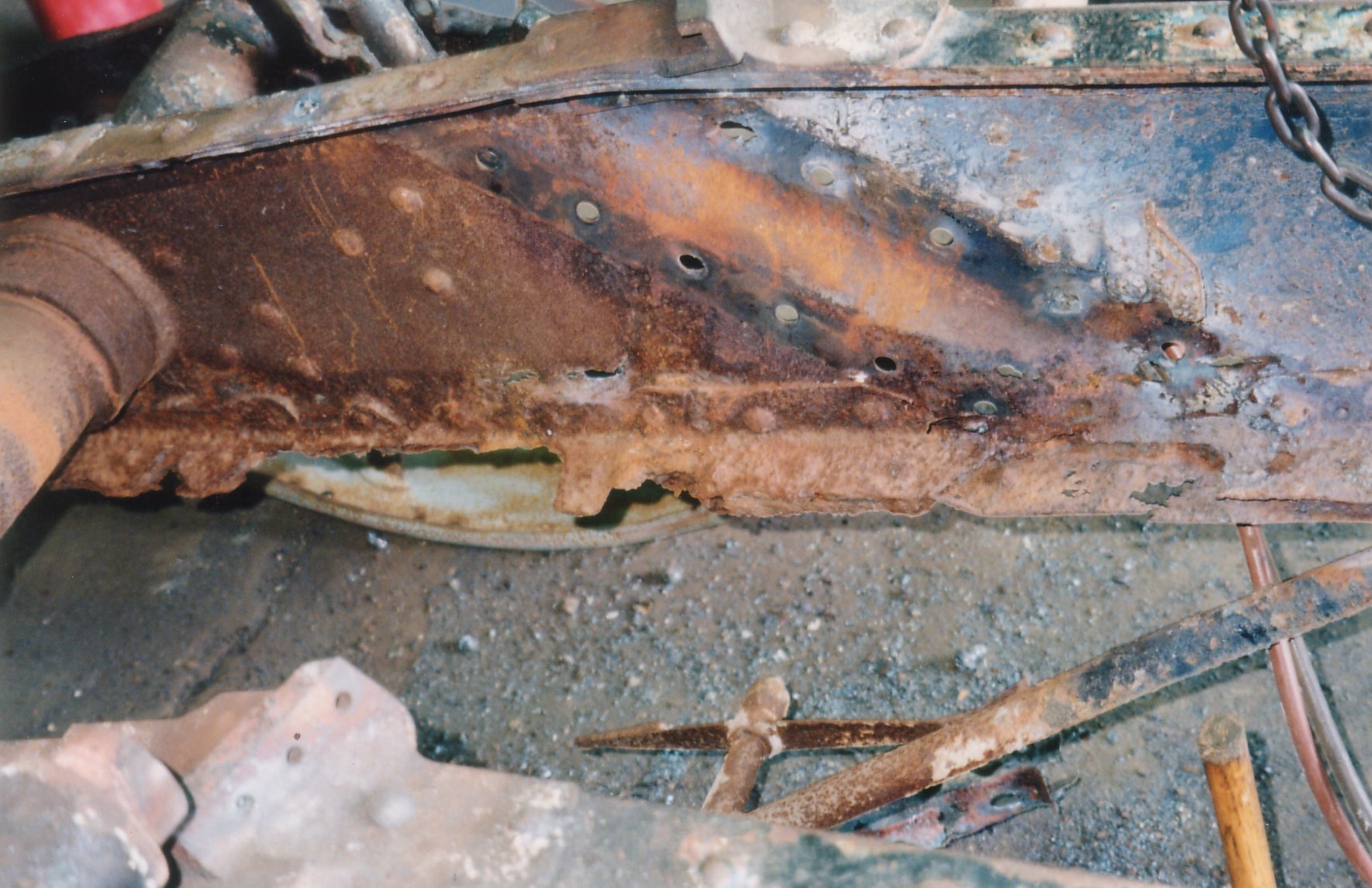
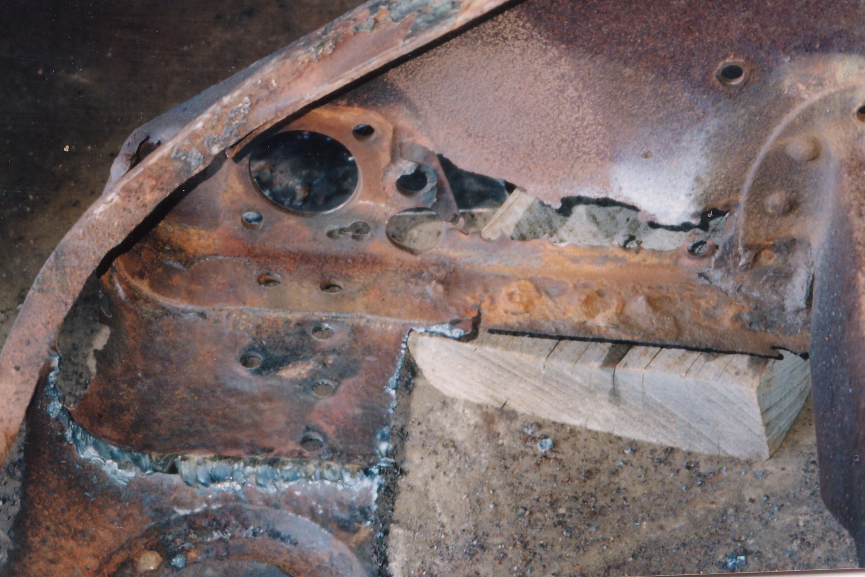
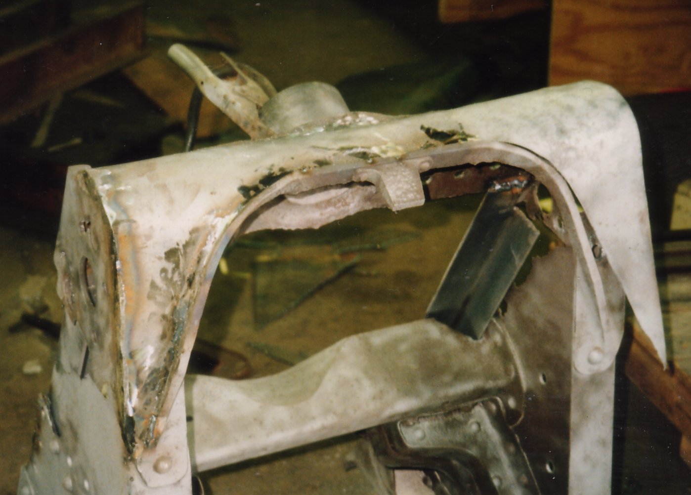
With the sheet metal and the equilibrator/equilibrator mount stripped away the damaged carriage frame is visible. A new angle iron frame replaced this area.
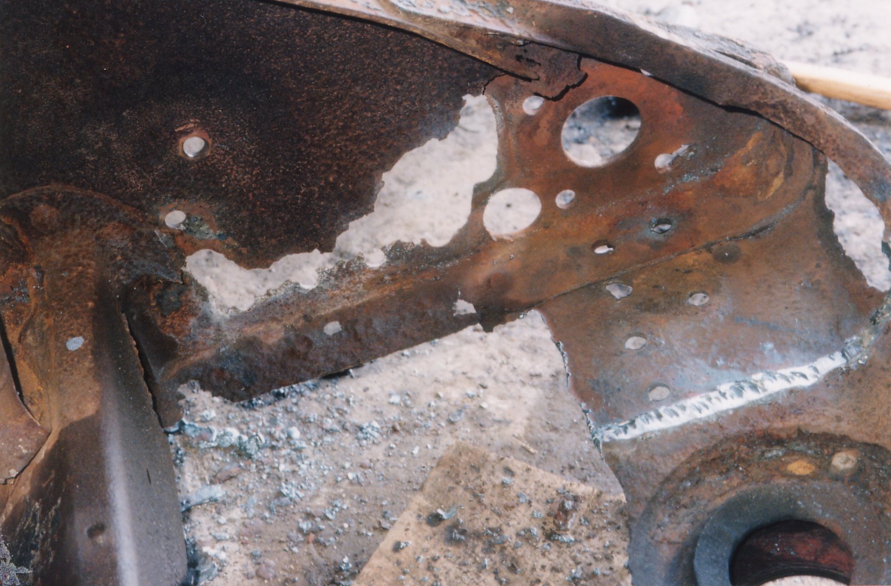
Another view of the damaged area.
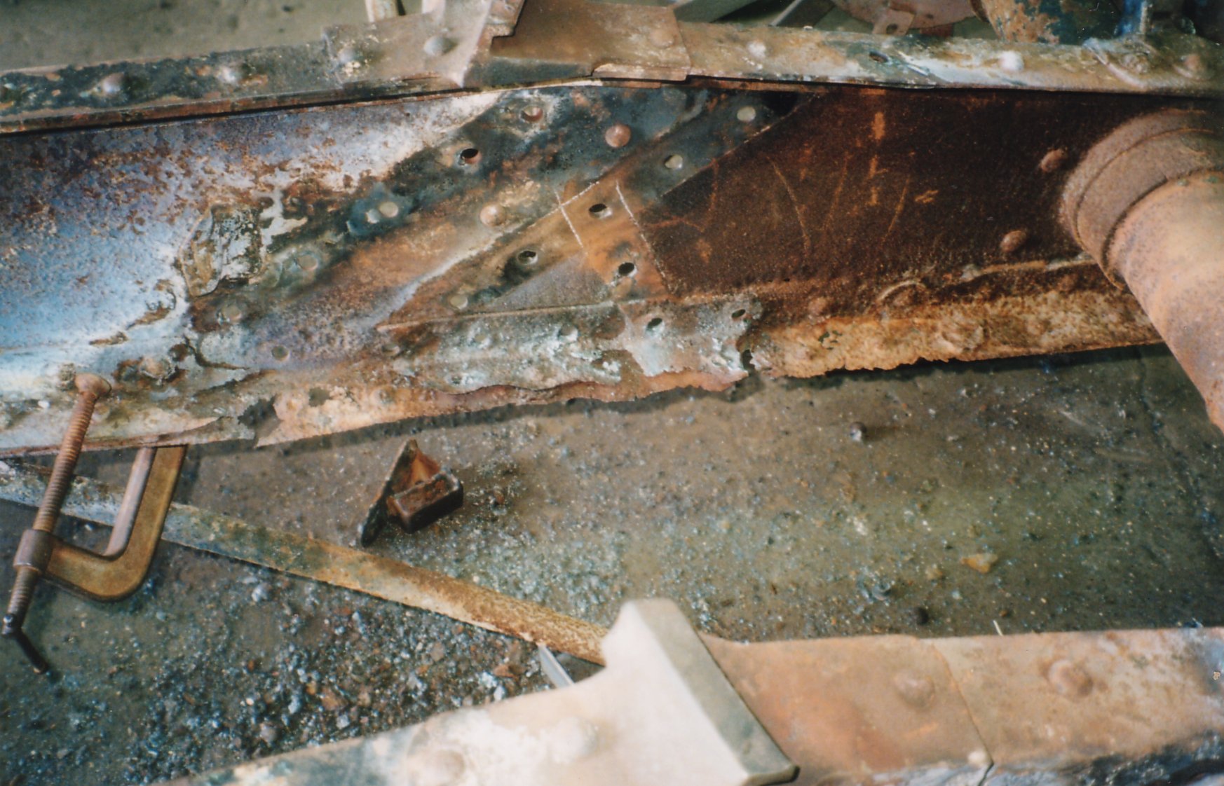
Ralph Lovett working on the same area of the carriage seen above but with new sheet metal riveted into place.
Ralph Lovett heating rivets on the side of the carriage. Notice, under the carriage axel, there is a pivot mount supported by a tubular A-Frame. This is the 360 degree traversing mount for anti-aircraft/balloon service. This system was seldom used with the 10cm K 17 and I understand that no 10cm K 17s were actively employed as anti-aircraft guns. It seems unusual, in the austere late-war environment this piece was designed and manufactured in, that this piece was retained.
A close up of the newly riveted sheet metal coving the equilibrator area of the carriage. (The A-Frame anti-aircraft mount can once again be seen underneath the carriage)
The recoil cradle with the recoil mechanism and barrel removed. A great deal of work was necessary to get to this point. The trunnions were damaged when the barrel was pressed out. Realigning the trunnions was a very difficult and expensive process.
The recoil cradle after sandblasting.
The recoil cradle with damaged sheet metal visible. This area was later re-riveted and new sheet metal put in place.
A rear view of the damaged sheet metal, with the poorest area cut away.
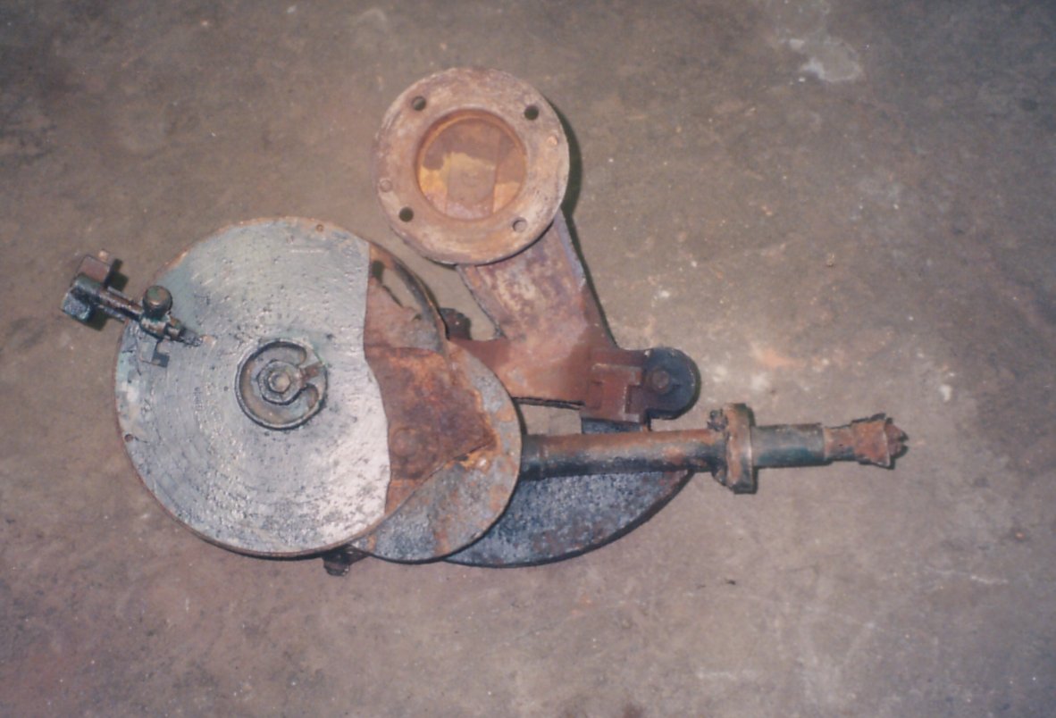
The range drum/sightmount. This is the device that gives the gunner the correct quadrant (elevation) for the gun barrel before firing.
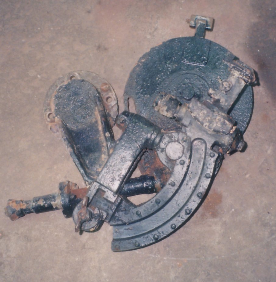
A side view of the range drum/sightmount. The range drum is essentially a mechanical computer. The needed range is set on the disk like piece. This in turn moves the arch which also serves as the panoramic sight mount. The gunner then elevates the barrel until his panoramic sight bubble is level. The barrel is then at Range Elevation. Sight Elevation is added by figuring the difference between the gun elevation and the target’s elevation. A gunner’s quadrant could be used to check Range Elevation plus Sight Elevation.
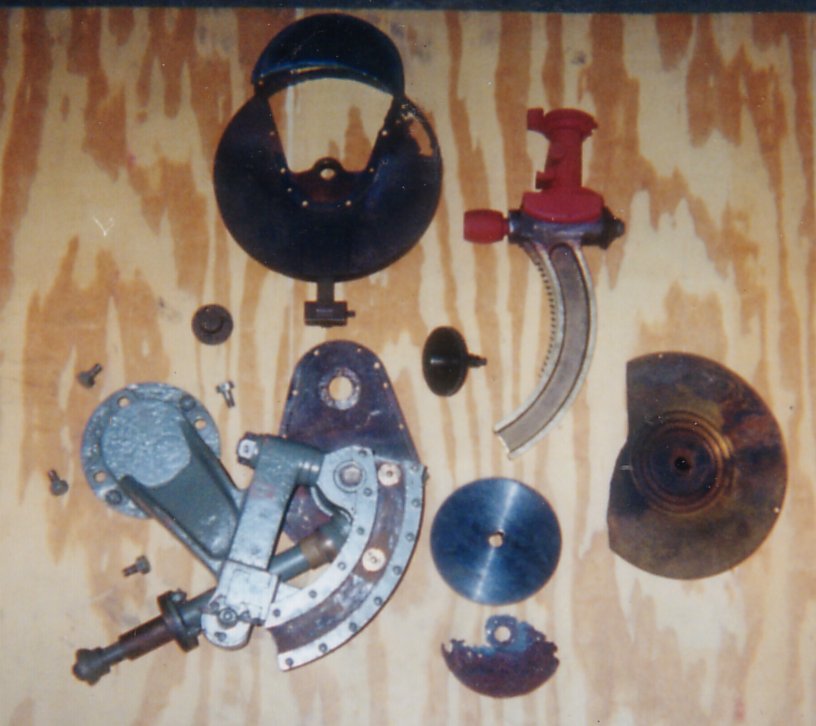
The range drum disassembled and cleaned. The main part of the mount is primed and painted. The panoramic sight holder/arch is painted with red oxide primer in this photograph.
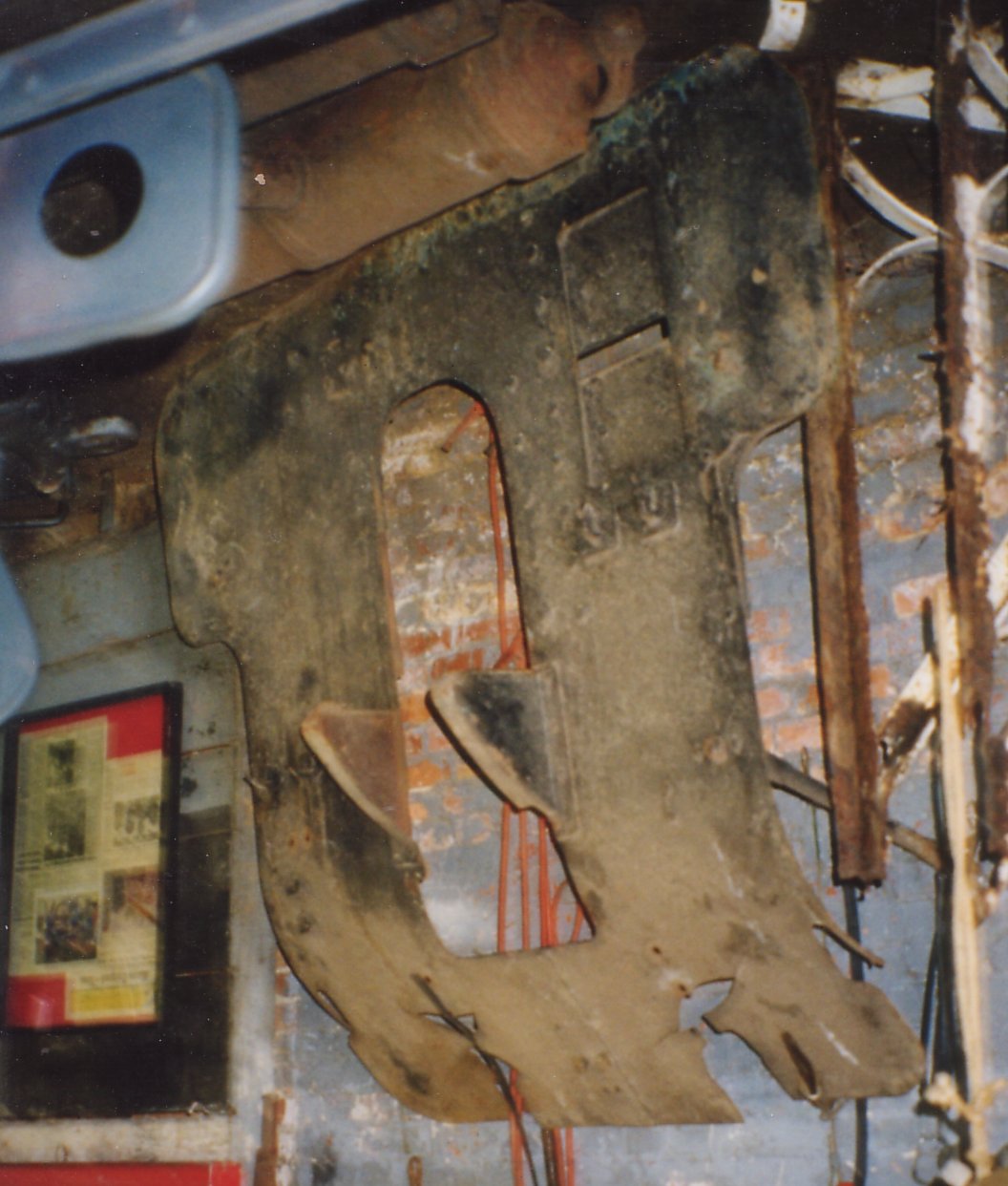
The damaged shield removed from the gun.
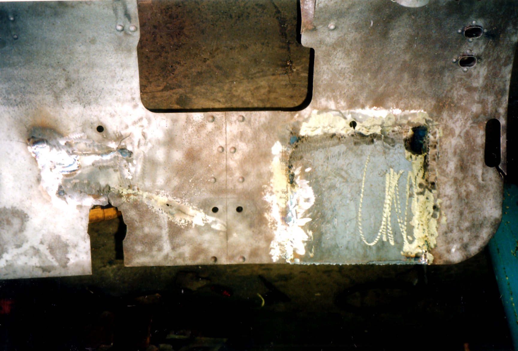
The first of several patches welded into place on the gun’s shield.
The new spade riveted to the original mount underneath the gun’s carriage.
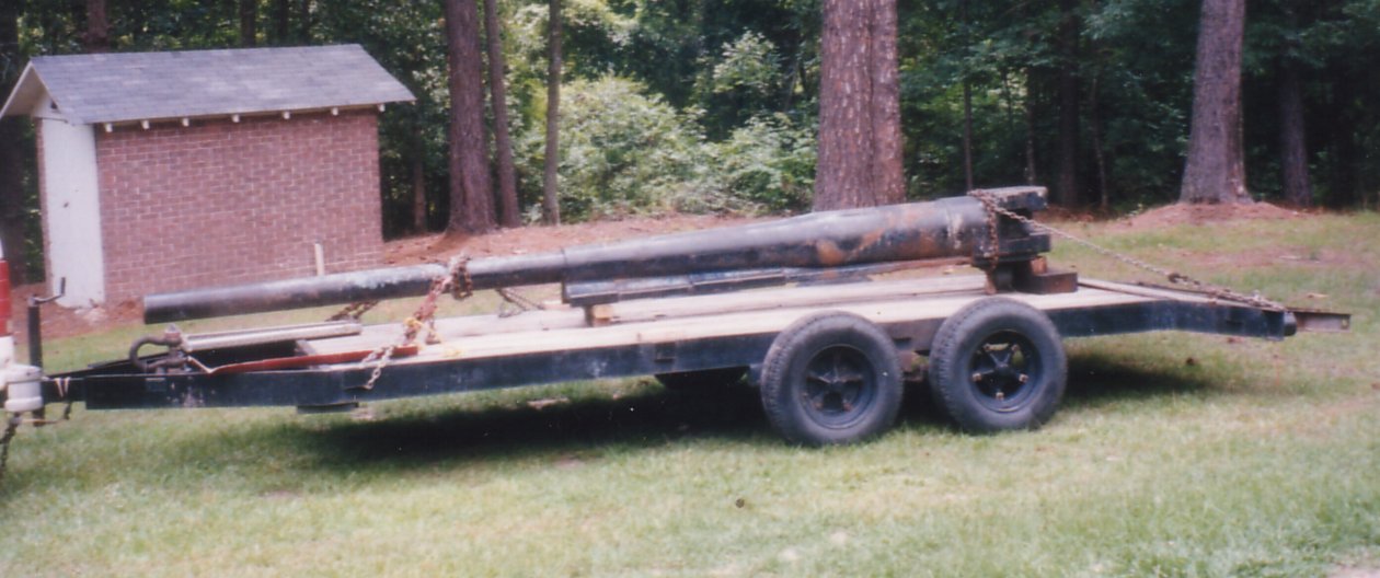
The barrel and breech ring for the 10cm Kanone.
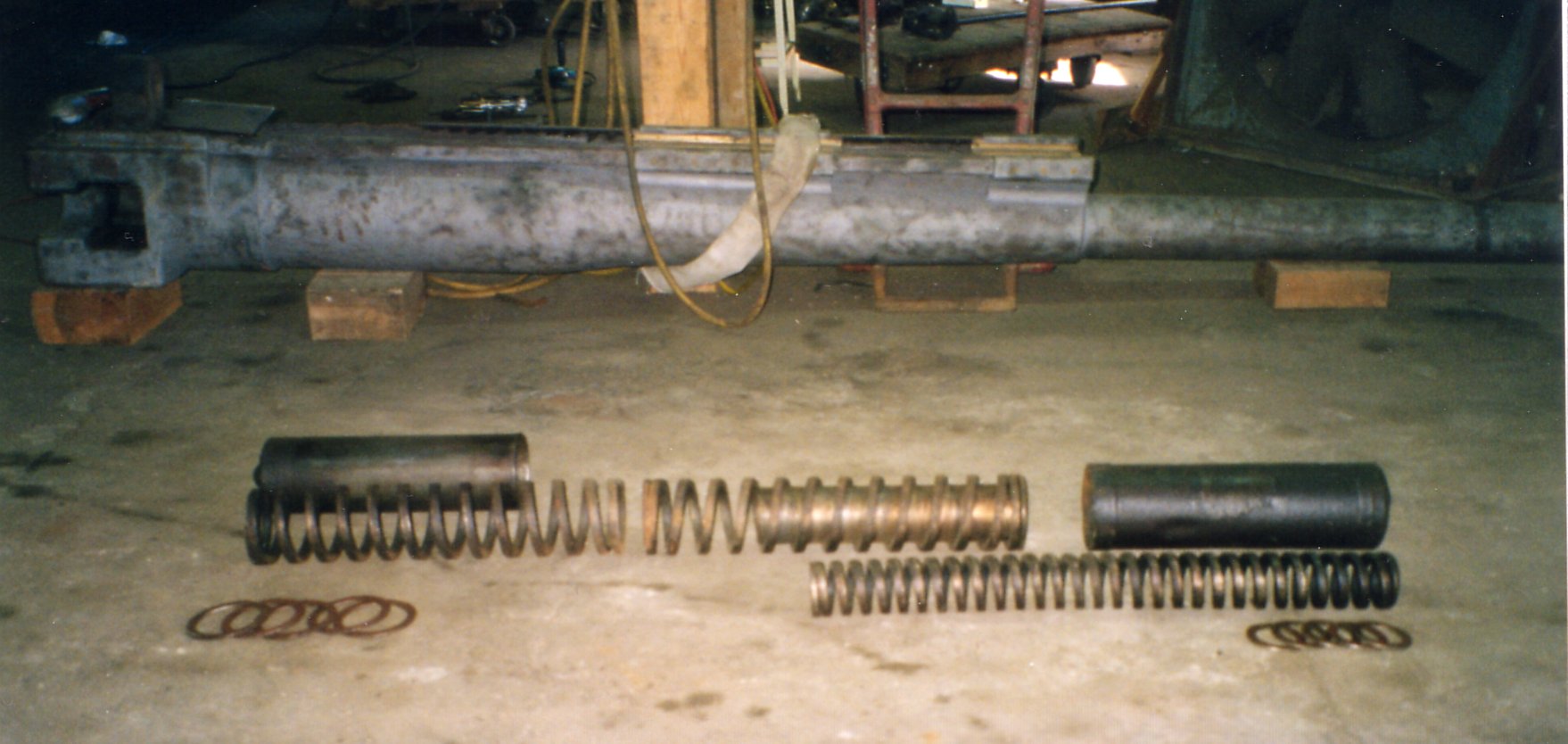
The equilibrator disassembled in front of the 10cm barrel. Note this is not the recoil mechanism.
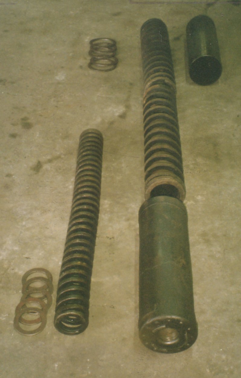
Another view of the equilibrator.
The equilibrator and elevation gearing all back in place and working.
Sliding the barrel into the recoil cradle. Leon Lovett is to the side of the gun.
Ralph Lovett stops for a moment to get a photograph of the barrel sliding back into battery.
A rear view of the 10cm. Kanone with the barrel back in battery. The barrel is connected to the hydro-spring recoil mechanism. The sheet metal patches riveted onto the recoil cradle are seen in this photograph. Also, notice the newly rebuilt wooden wheels now fitted onto the gun.
To see this 10cm. Kanone 1917 after the restoration
All images, research, and text are sole property of Ralph Lovett.